Ionosphere
Ionosphere is an interactive exhibit created out of a partnership between The Science and Engineering Education Center and The William B. Hanson Center for Space Sciences at UT Dallas. Our goal was to introduce the effects the Ionosphere has on radio transmissions to elementary and middle school students.
Build Process
The design and build process of Ionosphere was a collaborative effort that reflected a teaching faculty member's reasearch on how the Ionoshere can affect radio wave transmission across the globe. Our goal was to represent how radio waves are reflected off of the ionosphere to distant recieivers, and how changing conditions of the ionosphere due to weather or season can change how radio waves interact and reflect off of the ionosphere.
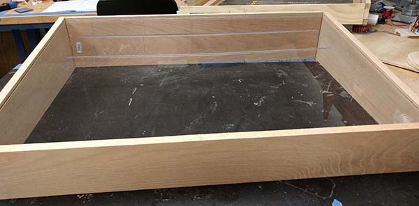
In order to represent radio waves, we decided to use lasers, and to represent the radio waves (lasers) bouncing off the ionosphere, the ionosphere became a single movable mirror.
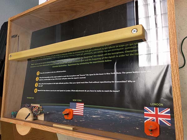
Now it was time to prototype and test the radio recievers and electronics package. The "radio recievers" were created using 3D printing and were based off of an ionosphere reasearch antennea. The final version of the recievers were redesigned to look more like the standard dish antennea to help with public perception about what they were representing.
The electonics started off as a Arduino Nano along with two photoresistors and two LEDs. It was then programmed so that when the photoresistors reached a certain point above ambient light, they would turn the LEDs on to simulate the radio waves being recieved by the station.
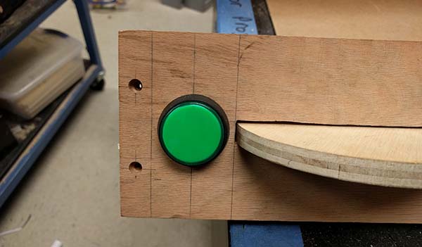
Once the electronics were finished and tested, I added the laser button and laser wheel to the front of the exhibit. The button, when pressed, turns the laser on for 45 seconds. Then, users can turn the wheel to change the direction of the laser and try to get the laser to bounce off of the mirror and hit a reciever.
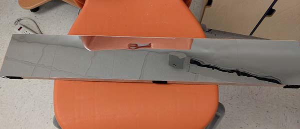
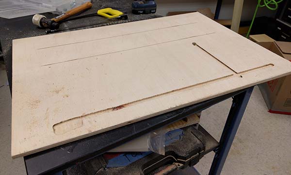
Another important part of this exhibit was the movable mirror that represented the ionosphere. Here you can see a close up of the mirror, the velcro padding on the bottom (which is actually the top) is used as padding between the wooden portion of the mirror and the plexi cover on the top of the exhibit.
In this image the placement of the mirror is also visible, as well as the prototyped handle for moving the mirror.
Lessons Learned
This project was a fun challenge that involved multiple departments and many many man hours. Overall, from inception to delivery, this project took almost 6 months. The majority of that time was spent ironing out the vision and requirements for the project as well as working through the the message we wanted to use. We also wanted to make it accessible to the population that we serve.
From fabrication start to finish, it took about 3 months. There are always lessons learned when creating projects, and this was no exception.
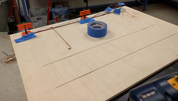
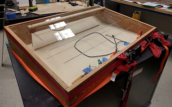
One of the biggest lessons I learned from this project was related to the wiring and the microcontroller placement. As you can see above, the microcontroller and wiring were placed below the laser wheel in an attempt to keep the wiring hidden and out of sight. However, halfway through the project we decided to swap from the tiny Arduino Nano to a much larger TI Launchpad in order to stay standard across our other exhbits and their statistics gathering devices.
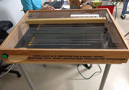
This change led to a much larger electronics package that ended up being much more visible then originally intended. Originally, the entire electronics package was going to fit below the bottom cover. Instead of leaving the electronics where they were, I would rather have placed them in the back corner of the exhibit in a black enclosure to hide them from view. Unfortunately, this exhibit was planned for deployment, and we had to instead simply cover the electronics in place with plastic sheets. Future repair or modification will include moving the electronics to a more discreet area in the exhibit.